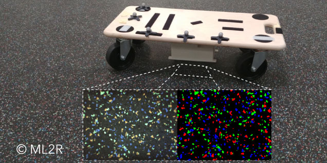
The dynamic transport of goods in warehouses poses a significant problem in logistics. It involves transporting goods from a warehouse to the location where they are needed. To solve this problem with autonomous robots, they must be able to navigate the hall safely. Essential for route planning is their localization. This is particularly challenging in larger halls where reference points are missing. Since global localization (i.e., determining the position in the hall) is crucial here, a method for robot localization using “floor cameras” (cameras facing the floor) was developed as part of ML2R (now the Lamarr Institute). For this purpose, the floor camera recordings are processed using a Machine Learning pipeline to map a position in space to an image. Since a position in space can be assigned to each image, it is now possible to solve the kidnapped-robot-problem in each frame. This means that the robot can determine its position without any prior knowledge. Furthermore, global localization can be performed directly on the robot. We will explain how this works in more detail below.
Three steps to global localization
There are various research approaches for the localization of autonomous robots to navigate within a space. One approach that we consider within the scope of ML2R (now the Lamarr Institute) is localization using a floor camera attached to the underside of the robot. The approach is tested in the large research hall for “Cellular Conveying Technology” (Link in German) with a special industrial floor covering. This floor covering has randomly distributed color spots and was selected to facilitate floor localization and to test it in principle. The random distribution creates unique combinations of color spots on the floor, which simplify robot localization. In the approach we developed, the robot localizes itself within a space in three steps.

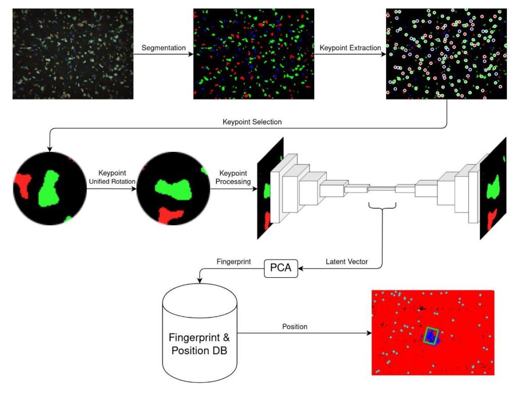
Overview of the designed pipeline for ground localization in three steps.
First, all relevant keypoints (recognizable features) are extracted from the image captured by the floor camera. In the next step, a unique identifier called a fingerprint is generated from each keypoint. It is important that the same keypoints in different images produce a similar fingerprint, regardless of how the image is rotated or where they are located in the image. In the final step, the position of the robot is determined using a database. Below, we will explain these three steps in more detail.
Step 1: Creation of all keypoints of the image
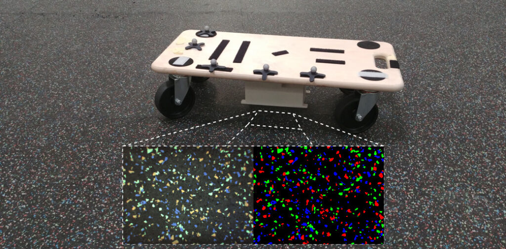
The system is tested in a hall equipped with a special floor with a dark base color and various color spots. The robot can capture an image of the current floor section using the floor camera. A mask of the different color spots is generated from the image using a segmentation network. An example of an image from the floor camera and its recognized mask is shown in the figure below. The features to be recognized in the images are local and therefore lie within a small image section. Therefore, a shallow CNN (Convolutional Neural Network) for segmentation is sufficient. The floor is segmented into red, blue, and green masks (images with color spots of a color). In the next step, the connected areas of the individual color spots are recognized from the masks. The centers of these color spots are used as recognizable features, keypoints, and further processed.

Test setup for recording the ground images and position data.
Step 2: Generation of fingerprints
To generate fingerprints, an autoencoder is used, which compresses the uniformly rotated area around a keypoint into a latent space. The goal is to obtain, on the one hand, a similar latent vector within the latent space for the same keypoints, regardless of the rotation of the robot, and on the other hand, to obtain as different latent vectors as possible for different keypoints. To achieve this, a loss function is used during the training of the Machine Learning pipeline:
$L_{rec} = frac{1}{n}sum_{i=1}^{n}(y_i- tilde y_i)^2$
The reconstruction loss (Lrec) is the mean squared deviation of the image reconstructed by the decoder and the original image. The smaller the squared deviation, the more similar the reconstruction is to the original image. To generate fingerprints, the encoder is used to generate a latent vector from the environment around a keypoint.

Structure of the autoencoder: The input and output is the mask after segmentation in an area of 64 pixels around a keypoint.
The latent vector is the compressed representation of the environment of a keypoint and has too large a dimension as a fingerprint. Therefore, it is subsequently reduced to a size of up to 10 using PCA (Principal Component Analysis).
Step 3: Database creation and position search
To create the database, recordings and positions of the floor camera attached to the robot are required. This is realized with a camera synchronized with a motion capture system. The obtained images are then processed into keypoints. With the position of the image in the hall and the pixel coordinates of the keypoints, the position of the keypoints on the hall floor is then calculated. The corresponding fingerprints are then generated for the keypoints in the next step. Subsequently, the generated pairs of fingerprints and positions are used to create the database. The database itself is designed so that the most similar existing fingerprints and their positions can be quickly found for a given fingerprint. To achieve this, a k-d tree is used here.
The position of a captured image can then be determined by querying the k-d tree. The position in the hall is determined for each fingerprint from the image by determining the positions of the nearest three fingerprints from the database. With the position candidates thus determined, the position of the capture in the hall can be estimated.

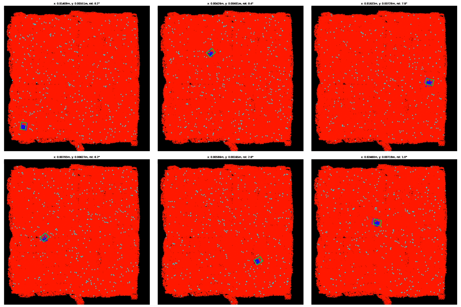
In the presented video, a run of our position determination is shown. The red dots represent the positions of all fingerprints in the database. The purple rectangle represents the correct position, and the green one represents the estimated position of the capture. The blue dots are the determined position candidates of the fingerprints from the database. The average deviation of the correct position from the estimated position is approximately 10 millimeters.
The presented project shows: Localization based on a floor camera is possible under laboratory conditions. The division of position determination into the three parts of keypoint creation, fingerprint generation, and subsequent database search is promising. Keypoint creation is important for finding unique features that the robot can orient itself by. Since there is a special floor in this Lamarr project, segmentation is used to utilize the color spots as keypoints. Each keypoint consists of a position and its surroundings. To find a position based on a keypoint environment, a database is used. To achieve this efficiently, the dimension of the keypoint environment must be reduced. For this purpose, an autoencoder and PCA are used. In the future, the project will be continued to evaluate and further optimize the system with more data and a larger area.

